
Custom Sheet Metal Fabrication From Your Drawings
ShincoMetal manufactures custom sheet metal parts, enclosures, brackets, panels, and fabricated assemblies from customer drawings.
We review cutting, forming, welding, hardware, finishing, inspection, and assembly as one project scope. This helps identify manufacturing constraints, critical interfaces, and responsibilities before production begins.
Is Your Project a Good Fit?
Our service is intended for drawing-based equipment parts, electronics enclosures, industrial components, and fabricated assemblies, from prototypes through repeat production.
Use the following values only as an initial screening reference. Final acceptance depends on material condition, geometry, feature size, tooling access, finishing, inspection requirements, and the controlling drawing.
| Project requirement | Capability proposed for confirmation |
|---|---|
| Aluminum fabrication | 5052-H32 formed parts and 6061-T6 plates; approximately 0.8–6.0 mm sheet thickness, depending on operation and geometry. |
| Stainless steel fabrication | 304/304L and 316/316L, approximately 0.5–4.0 mm sheet thickness, subject to forming and welding requirements. |
| Carbon and galvanized steel | Approximately 0.5–6.0 mm sheet thickness, subject to grade, surface condition, and manufacturing route. |
| Copper and brass components | Approximately 0.5–3.0 mm sheet thickness, subject to alloy, temper, conductivity requirements, and part design. |
| Flat-part working envelope | Up to 3,000 × 1,500 mm for suitable cutting projects. |
| Formed-part envelope | Bend lengths up to 2,500 mm; available thickness depends on material, bend length, tooling, and geometry. |
| Order quantities | Prototypes from one piece, with repeat-production quantities quoted by part and demand forecast. |
Large parts, deep returns, enclosed bends, narrow flanges, dense features, and demanding cosmetic requirements may require a different production route. Send the drawing even when a part falls outside the reference ranges so that feasibility can be reviewed.
Manufacturing Services for Your Finished Part
A complete fabrication route connects the profile, bends, joints, hardware, surface treatment, inspection, and assembly requirements.
The quotation should identify:
- Which operations are included.
- Which operations are completed in-house.
- Which operations are completed by specialist partners.
- What inspection records or material documents are required.
- Which drawing revision and acceptance criteria control production.
This prevents a cutting-only quotation from being mistaken for a finished-component scope.
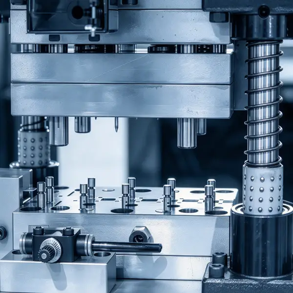
Laser Cutting and Punching
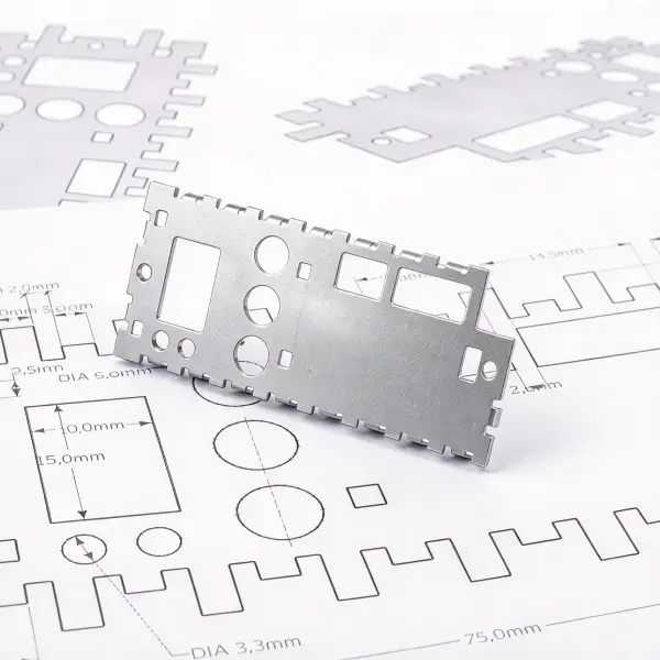
Laser cutting can produce outside profiles, connector openings, ventilation patterns, holes, and slots. Material, thickness, smallest feature, edge condition, and downstream forming determine the production strategy.
Fiber laser cutting and CNC turret punching are available for suitable projects.
Repeated holes or formed features may justify punching when geometry, quantity, and tooling requirements support that route.
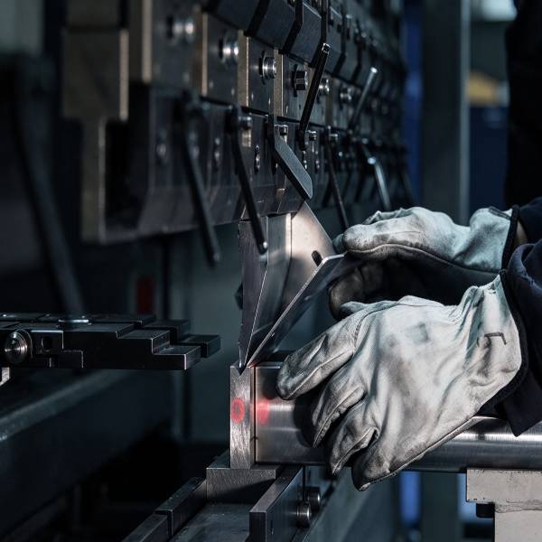
CNC Press Brake Forming
Forming feasibility depends on bend radius, flange length, material condition, relief geometry, bend sequence, and tool access.
Before production, we review:
- Short flanges and return bends.
- Holes or slots close to bend lines.
- Tool interference and enclosed features.
- Hardware access after forming.
- Dimensions that must be controlled in the final formed condition.
CNC press brakes with geometry-specific tooling are available.
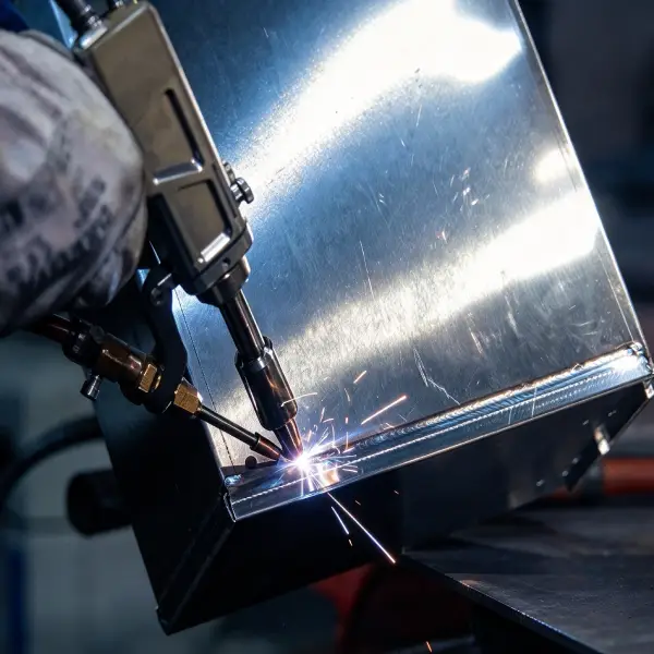
Welding, Hardware, and Fabricated Assemblies
Joint design, fit-up, fixturing, welding sequence, and heat input can affect mounting faces, flatness, and squareness.
TIG and MIG welding are available for suitable carbon steel, stainless steel, and aluminum projects.
Continuous welds do not by themselves establish leak-tight, pressure-rated, or structural performance. Any such requirement must include an agreed design basis, inspection method, and acceptance criteria.
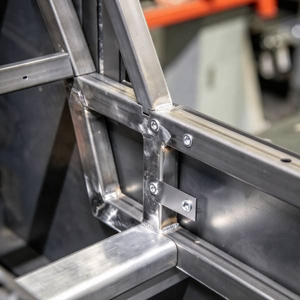
Hardware, Threads, and Assembly
Self-clinching nuts, studs, standoffs, tapped holes, and countersinks must remain accessible and functional after forming and finishing.
Selection depends on sheet thickness, hardness, edge distance, installation direction, and final assembly access.
For multi-part projects, provide a bill of materials identifying fabricated parts, purchased hardware, and assembly responsibilities.
Hardware installation and assembly are available for suitable projects.
Materials Matched to the Design
Aluminum
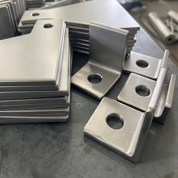
5052-H32 is commonly selected for formed enclosures because it generally supports bending better than 6061-T6. When 6061-T6 must be bent, the alloy condition, radius, grain direction, and cracking risk require closer review.
Carbon Steel
Grade, surface condition, stiffness, weldability, coating compatibility, and corrosion protection should be considered together.
Stainless Steel
Selection between 304/304L and 316/316L depends on exposure, cleaning, welding, finish, and corrosion requirements. A material name alone does not establish suitability for a particular environment.
Copper and Brass
Alloy, temper, conductivity, bend integrity, contact finish, and surface appearance can affect both manufacturing and final function.
Tolerances Defined Around Functional Interfaces
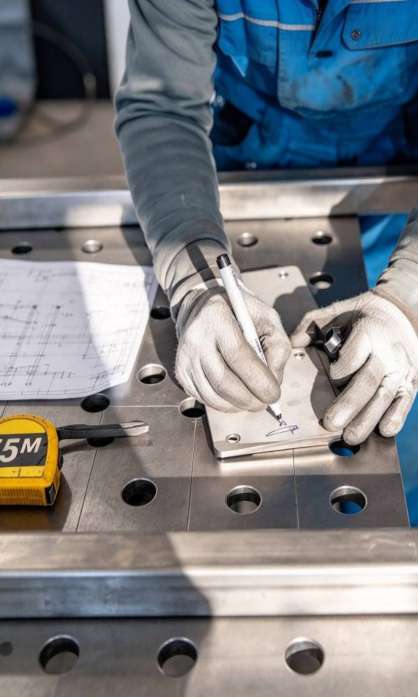
Tolerance requirements should follow part function rather than applying one value to every feature.
The following values are quotation references, not blanket guarantees:
| Feature | Proposed reference | Review conditions |
|---|---|---|
| Laser-cut feature location | ±0.10 mm | Material, thickness, feature size, datum system, and spacing |
| Formed linear dimension | ±0.30 mm | Bend count, flange geometry, tooling, setup, and measurement condition |
| Bend angle | ±1° | Material, radius, flange length, springback, and tool access |
| Welded assembly | Drawing-specific review | Fixture references, welding sequence, overall size, and measurement setup |
| Finished interfaces | Final-treatment review | Coating build, masking, threads, holes, and mating clearances |
Finishing Without Losing Functional Fit
| Finish | Application considerations |
|---|---|
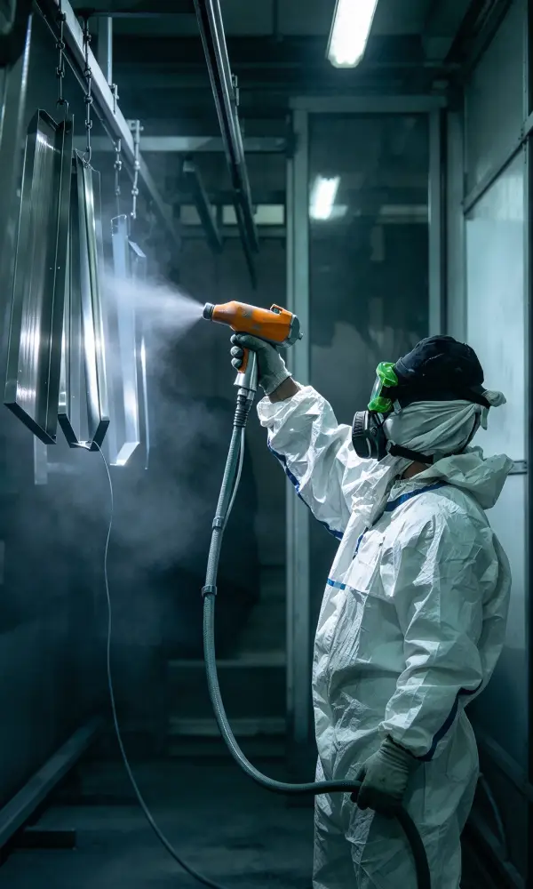
| Powder coating | Color, texture, gloss, coating build, visible faces, edges, and masking |
| Anodizing | Alloy, type, color, appearance variation, masking, and dimensional allowance |
| Plating | Substrate preparation, coating system, contact areas, coverage, and dimensional effects |
| Passivation | Stainless grade, surface condition, specified process, and documentation |
| Brushing | Grain direction, visible faces, weld appearance, and handling requirements |
Proposed production responsibility:
- Powder coating: in-house.
- Painting: in-house.
- Silk screening: in-house.
- Anodizing, plating, electrophoresis, and passivation: completed by qualified specialist partners.
Threads, electrical contacts, grounding points, close-fitting holes, and mating surfaces should be identified before finishing.
Quality Checks Connected to Your Drawing
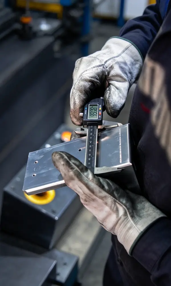
Inspection should focus on features that determine fit, assembly, and function.
Proposed inspection resources include calibrated calipers, micrometers, height gauges, surface plates, thread gauges, angle measurement tools, and suitable fixtures.
| Requirement | Proposed inspection approach |
|---|---|
| Mounting and connector features | Check feature size and location from identified datums |
| Formed flanges | Check selected lengths and angles in a defined setup |
| Welded assemblies | Check interfaces, diagonals, squareness, flatness, or fixture-defined points |
| Threads and hardware | Confirm identity, installation, position, and thread usability |
| Cosmetic surfaces | Compare agreed visible areas against documented acceptance criteria |
First-article reports, material documentation, certificates of conformity, and finish records can be supplied when agreed during quotation.
ShincoMetal holds ISO 9001:2015 certification covering relevant manufacturing activities.
A photograph can illustrate a process or surface condition, but it does not prove dimensional compliance. Inspection records should identify the drawing revision, measured feature, method, acceptance limit, and result.
From Drawing Review to Repeat Production
- Send the project package.
Include the model, dimensioned drawing, revision, material, finish, quantities, hardware, documentation requirements, destination, and target date. - Resolve manufacturing questions.
Review bend access, material condition, weld distortion, finishing allowance, critical interfaces, and inspection requirements. - Confirm quotation scope.
Align tooling, external processing, assembly, inspection records, packaging, delivery terms, and exclusions. - Approve prototype or first article.
Define the features and records that must be accepted before repeat production. - Produce against the approved revision.
Keep the purchase order, drawing package, and approved changes aligned.
Lead Times and Delivery Planning
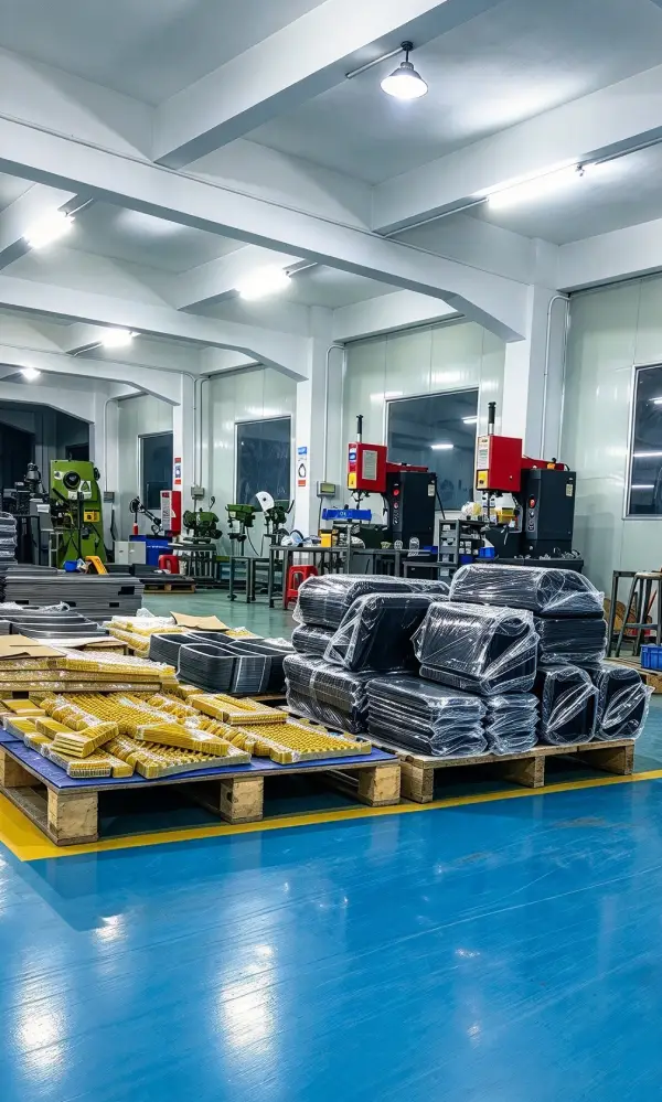
Lead time depends on material availability, geometry, quantity, tooling, finishing, inspection, approval stages, packaging, and destination.
| Project type | Proposed production window |
|---|---|
| Simple cut-and-bent prototypes | 5–10 working days |
| Prototypes with welding, hardware, or finishing | 10–15 working days |
| Repeat production | 15–25 working days |
Production time begins only after the technical scope, price, drawing revision, and required approvals have been agreed. [To be confirmed] International transport and customs time are excluded from these references.
DDP delivery is available for applicable destinations and orders.
Applications for Custom Sheet Metal Parts
Electronics Enclosures and Panels
Projects may involve connector access, mounting alignment, ventilation, grounding, masked contacts, and cosmetic surfaces.
IP, EMI, and thermal performance require separately defined design responsibility and test evidence. Fabricating an enclosure does not by itself certify these performance levels.
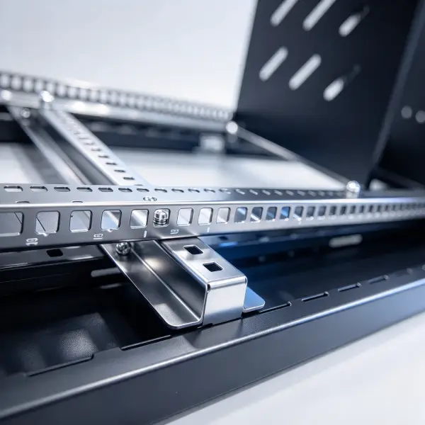
Equipment Brackets, Frames, and Supports
Important considerations include mounting interfaces, load paths, joint design, hole position, weld distortion, and final assembly fit.
Load capacity and fatigue performance require suitable design or validation evidence beyond routine fabrication inspection.
Busbars and Conductive Components
Busbars and conductive parts require defined electrical requirements, material and temper, bend integrity, contact finish, edge preparation, and mechanical fit.
Frequently Asked Questions
What files should I send for a quotation?
Send STEP or STP where available, a matching dimensioned PDF, and DXF or DWG for relevant flat profiles. Include material, thickness, finish, quantity, critical dimensions, hardware, documentation, target date, and destination.
Can I request a prototype before production?
Yes. Prototype orders can begin from one piece. State whether the prototype is intended to check the profile, assembly fit, finish, or complete function so that the quotation includes the correct scope.
Do you offer one standard tolerance for every part?
No. Tolerance feasibility depends on the material, thickness, feature, forming sequence, welding, finishing, datum structure, and measurement condition. Critical requirements are reviewed against the drawing.
Can finishing and assembly be included?
Yes, for suitable projects. The quotation should identify which finishing processes are completed in-house or by specialist partners and define the included assembly responsibilities.
Request a Quote for Your Custom Sheet Metal Parts
Send your drawings and project requirements for a fabrication quote. Include the material, thickness, quantity, finish and delivery destination so we can review the scope.
Factory Address
Building 1, No.8, Second Street, Huangjiang Town,
Dongguan City, Guangdong Province
Email
contact@shincometal.com
Phone / WhatsApp
+86 13392819510
Factory Visits
Please contact us in advance to arrange a factory visit.